
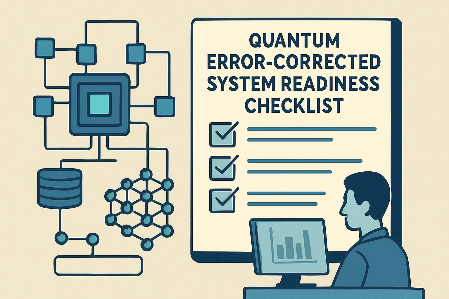
Quantum Error-Corrected Systems: Readiness Checklist
Introduction
Production quantum computing teams chasing ever-higher physical qubit counts routinely discover that raw scale alone delivers neither reliable logical qubits nor useful fault-tolerant computation. The decisive differentiator is a disciplined quantum error corrected systems readiness posture built on logical qubit readiness, fault tolerance metrics, and decoder-aware code-distance benchmarks rather than headline qubit totals.
This article delivers a practical, evidence-led checklist that senior quantum hardware and systems engineers can apply today to separate marketing claims from deployable capability. You will finish with concrete metrics, a decision framework, failure diagnostics, and production-grade monitoring guidance that has been stress-tested against both superconducting and trapped-ion roadmaps.
A typical failure scenario: a vendor demonstrates a distance-5 surface code with 0.1 % physical error rate yet, under realistic cycle times and decoder latency, the logical error rate per round exceeds the target 10^{-6} needed for useful algorithmic depth. The result is a system that cannot run a single reliable T-gate sequence despite thousands of physical qubits. The checklist below prevents exactly this class of surprise.
Executive Summary
TL;DR: Physical qubit count is marketing; logical error rate below threshold at target code distance under realistic decoder and cycle-time assumptions is engineering truth for quantum error corrected systems.
- Logical qubit readiness must be proven at distance ≥5 with a decoder whose latency fits within the hardware cycle budget.
- Fault tolerance metrics should include both logical error rate per round and the error-suppression factor Λ between consecutive code distances.
- Code distance vs decoder assumptions dominate; an optimal decoder on paper can become unusable if its runtime exceeds hardware coherence limits.
- A production checklist must combine physical error rates, syndrome extraction fidelity, decoding latency, and logical benchmarking circuits.
- Realistic p95 cycle fidelity and crosstalk maps are mandatory inputs; idealized simulations mislead.
- Readiness is achieved only when a system can sustain algorithmic volume (logical qubits × depth) sufficient for the target application while maintaining logical error rates below 10^{-6}–10^{-8}.
Direct Answers for Common Queries
What is the single most important metric beyond physical qubit count? Sustained logical error rate per round at target code distance under production decoder latency and realistic noise including crosstalk and leakage.
How does code distance interact with decoder choice? Higher distance suppresses errors exponentially only if the decoder can process syndromes within the hardware cycle; otherwise the effective logical error floor rises sharply.
What readiness level is required before claiming fault tolerance? Demonstrable error suppression (Λ > 10) between distance-3 and distance-5 or distance-7 surface or color codes, with logical error rate < 10^{-6} at the higher distance while running a distance-scaled repetition code or magic-state distillation circuit.
How Quantum Error-Corrected System Readiness Checklist: Metrics That Matter Beyond Physical Qubit Count Works Under the Hood
At its core a fault-tolerant quantum computer encodes k logical qubits into n physical qubits using a quantum error-correcting code of distance d. The surface code remains the leading candidate because of its high threshold (~1 % under depolarizing noise) and planar layout compatibility with superconducting architectures. The logical error rate P_L scales roughly as (p/p_th)^{(d+1)/2} where p is the physical error rate and p_th the threshold. This exponential suppression is the theoretical foundation, yet real systems deviate because of correlated errors, leakage, and decoding latency.
The readiness checklist therefore decomposes into four interdependent layers:
- Physical Layer Metrics: two-qubit gate fidelity, readout fidelity, coherence times (T1, T2), crosstalk matrix, leakage population. These must be measured at scale on the exact device that will run the code.
- Syndrome Extraction Layer: parallelizable stabilizer measurement circuits with ancilla reuse. The circuit depth and error accumulation during syndrome rounds must be characterized; a single faulty syndrome round can destroy the exponential suppression.
- Decoding Layer: minimum-weight perfect matching, union-find, or neural-network decoders. The decoder must finish within the hardware cycle time (typically 1–10 µs). If it cannot, the system must either pipeline decoding (increasing latency) or accept a higher logical error floor.
- Logical Benchmarking Layer: distance-scaled repetition codes for memory experiments, logical randomized benchmarking, and magic-state injection and distillation circuits. These provide the only ground-truth logical error rate benchmark.
Text diagram of the readiness stack:
Application Volume Requirement
        ↓
Logical Benchmarking (error rate, Λ, magic-state fidelity)
        ↓
Decoding Latency & Accuracy (decoder runtime < cycle time)
        ↓
Syndrome Extraction Circuit (parallelism, ancilla reuse, leakage)
        ↓
Physical Device Map (fidelities, crosstalk, T1/T2 at scale)
Our earlier Quantum Error Correction Readiness: Judging Logical-Qubit Claims explores how vendors often publish only the first and last layers while omitting decoder assumptions.
Implementation: Production Patterns
Begin with a minimal viable logical qubit. The following pseudo-code illustrates a surface-code memory experiment pipeline that can be incrementally hardened into a production readiness gate.
# Python / Qiskit-style pseudocode for distance-d surface code memory experiment

def run_surface_code_memory(distance, physical_error_model, decoder, rounds=1000):
    code = SurfaceCode(distance=distance)
    logical_qubit = LogicalQubit(code)

    syndrome_history = []
    for r in range(rounds):
        syndrome = measure_stabilizers(logical_qubit, physical_error_model)
        syndrome_history.append(syndrome)
        correction = decoder.decode(syndrome_history)
        apply_correction(logical_qubit, correction)

    logical_error = detect_logical_flip(logical_qubit)
    return logical_error, decoder.latency_stats()
Production hardening steps:
- Instrument every physical gate and readout with per-cycle fidelity metadata.
- Inject realistic leakage and crosstalk into the error model; ideal depolarizing simulations hide >30 % of observed logical failures.
- Measure decoder wall-clock time on the control-system CPU or FPGA; if >0.6× cycle budget, switch to a faster approximate decoder or add pipelining.
- Run distance triplets (d=3,5,7) and compute the observed suppression factor Λ = log(P_L^{d1}/P_L^{d2}) / log(d2/d1). Λ > 10 at target physical error is a strong readiness signal.
Advanced pattern: integrate real-time decoding with FPGA-based union-find. Several vendors have demonstrated <1 µs decoding for distance-5; this must be replicated on your hardware before claiming readiness.
For teams still operating in the NISQ regime, consult our Quantum Error Mitigation Decision Tree for NISQ to decide when to invest in full error correction versus continued mitigation.
Comparisons & Decision Framework
Different codes and platforms trade off threshold, connectivity, and decoder complexity. The checklist below helps choose.
| Criteria | Surface Code (Superconducting) | Color Code (Trapped Ion) | Decision Threshold |
|---|---|---|---|
| Threshold (depolarizing) | ~0.8–1.0 % | ~0.3–0.5 % | Physical p < 0.5× threshold |
| Connectivity required | 4-nearest neighbor | All-to-all feasible | Match to hardware graph |
| Decoder latency sensitivity | High (cycle ~1 µs) | Medium (cycle ~10–100 µs) | Decoder must finish <0.6× cycle |
| Logical error rate benchmark target | <10^{-6} at d=5 | <10^{-7} at d=7 | Application volume dependent |
Readiness Decision Checklist
- Is physical two-qubit error <0.5 % with crosstalk included? (Yes → continue)
- Can syndromes be extracted in ≤ d rounds with >99.9 % stabilizer fidelity? (Yes → continue)
- Does chosen decoder finish within 0.6× hardware cycle at d=5 on realistic syndrome streams? (Yes → continue)
- Is observed Λ ≥ 10 between d=3 and d=5 memory experiments? (Yes → continue)
- Can the system inject and distill magic states at logical error <10^{-6}? (Yes → logical qubit ready for algorithm test)
- Does the sustained logical volume (logical qubits × error-corrected depth) exceed application minimum? (Yes → production ready)
If any answer is “No,” the system is not yet a quantum error corrected system regardless of physical qubit count. Compare vendors using the same checklist in our Leading Quantum Computing Companies 2026: Definitive Comparison.
Failure Modes & Edge Cases
Common production failures include:
- Correlated leakage errors: a leaked qubit poisons multiple syndrome rounds. Mitigation: add leakage-reduction circuits (LRC) every 5–10 cycles; measure residual leakage population <0.1 %.
- Decoder overload under burst errors: cosmic-ray or control electronics transients. Diagnostic: monitor syndrome weight histogram; implement burst detection that pauses logical clock and resets.
- Drift beyond calibration window: T1/T2 and gate fidelity wander. Run weekly full-system tomography; set p99 fidelity gates to trigger recalibration.
- Optimistic simulation mismatch: decoder tuned on simulated noise fails on hardware. Always close the loop with hardware-in-the-loop training.
Edge case: distance-7 code with perfect decoder but 2 µs latency on a 400 ns cycle device yields effective logical error >10^{-3}. The checklist forces explicit latency budgeting.
Performance & Scaling
Key performance indicators for quantum error corrected systems:
- Logical error rate per round at target distance (target <10^{-6} for early FTQC).
- Error suppression factor Λ (target >10, ideally >20).
- Decoder latency p95 (must be <0.6 × cycle time).
- Logical volume = k_logical × d_effective (depth before logical failure probability exceeds 1 %).
- Overhead ratio n_physical / k_logical (target < 30 for distance-5 surface code with reasonable overhead).
Scaling guidance: once d=5 is reliable, move to lattice surgery or braiding for multi-logical operations. Monitor syndrome extraction fidelity at scale; crosstalk typically rises with larger arrays. p99 crosstalk below 0.01 % is a practical scaling gate.
Integrate with hybrid quantum-classical control planes; see our companion post on Hybrid Quantum-Classical Computing 2026: Nvidia DGX Architectures for orchestration patterns.
Production Best Practices
Security note: a fault-tolerant quantum computer can break RSA-2048 once it reaches ~few thousand logical qubits. Begin threat modeling now; our Quantum Computer Security: Physical Threat Models & Hardening details side-channel and calibration attacks on error-corrected hardware.
Testing: maintain a nightly logical-memory regression suite across three code distances. Use logical randomized benchmarking (LRB) and cycle benchmarking for gate-level logical fidelity.
Rollout: introduce logical qubits behind an abstraction layer that falls back to error-mitigated NISQ circuits until logical volume targets are met. Instrument runbooks with syndrome-weight alerts and automatic decoder fallback to minimum-weight perfect matching when neural decoders diverge.
Calibration cadence: physical layer every 4–12 h, syndrome-circuit validation daily, full logical benchmarking weekly. Automate drift detection with statistical process control on logical error trends.
Further Reading & References
- Google Quantum AI, “Suppressing quantum errors by scaling a surface code logical qubit,” Nature 614, 676–681 (2023).
- IBM Quantum, “Demonstration of error suppression with repetition codes,” arXiv:2406.02750 (2024).
- Quantinuum, “Logical computation demonstrated with a fault-tolerant trapped-ion quantum computer,” Nature 2024.
- Terhal, “Quantum error correction for quantum memories,” Rev. Mod. Phys. 87, 307 (2015).
- Fowler et al., “Surface codes: Towards practical large-scale quantum computation,” Phys. Rev. A 86, 032324 (2012).
- Our internal directory for vendor capability mapping: Definitive 2026 Directory of Quantum Companies.
Apply the checklist ruthlessly. Physical qubit count will continue to make headlines, but only teams that ship verifiable logical error rates below threshold will cross the fault-tolerance chasm. The metrics and patterns above are the practical difference between laboratory curiosity and production quantum error corrected systems.


